While on my last trip to Dayton, Ohio for the nations largest hamfest, I learned about the many great qualities of a Hexbeam antenna. My requirements in purchasing a HF antenna included:
- Good directivity
- Very light wind loading
- Reasonable cost
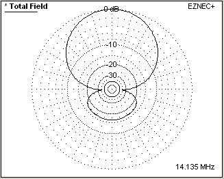
The hexbeam has a modest amount of gain averaging around 5 dBi and a front-to-back ratio around 14 dB. Since it’s made mostly out of rope and light wire, its wind loading is very small. For my purpose, I wanted to mount my antenna on a tripod, and given that a rotor was needed, this offered a very tight set of requirements.
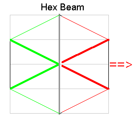
The hexbeam is essentially two wire elements (red and green) suspended in a “w” shape. The driven element defines the “front” side of the antenna (red) and the parasitic reflector provides the directivity (green). In my case, I have a multi-band hexbeam which is simply 5 hexbeams all stacked together. Each has a similar design but at increasingly larger sizes for the 10,12,15,17,20 meter bands. The resulting horizontal pattern is shown below (rotated counter-clockwise 90 degrees from the wire layout picture on the left).
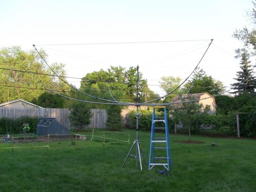
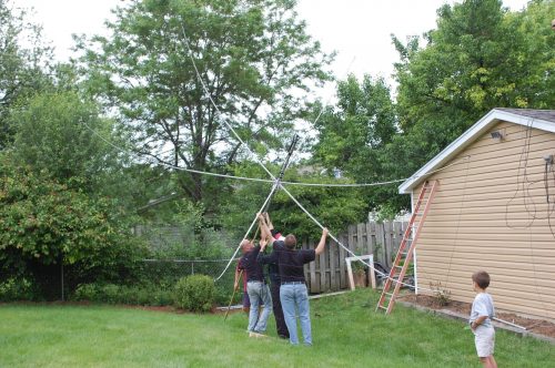
Building the antenna took a few days and it was assembled and tested on the ground.
A few neighbors helped lift it onto a temporary mast.
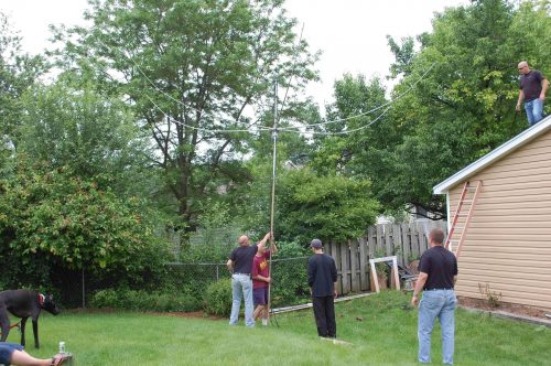
Then we lifted it from the ground up to another team on the roof of my garage.
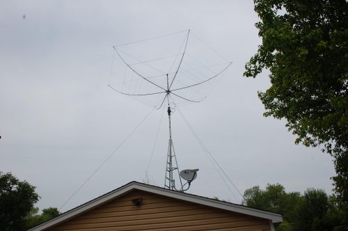
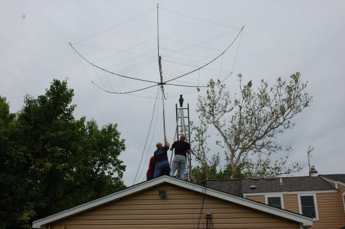
Once up on the roof, we positioned it alongside the 10 foot tripod.
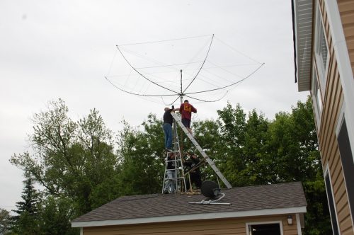
Then we lifted it straight up onto the rotor.
A mast mounted thrust bearing was used near the top with Dacron guy lines to help with lateral forces on windy days. This helped mitigate the rotor maximum load specification which was slightly exceeded. This was the result of using a longer-longer-than needed mast between the rotor and the antenna.